GPU Marching Cubes (Unity)
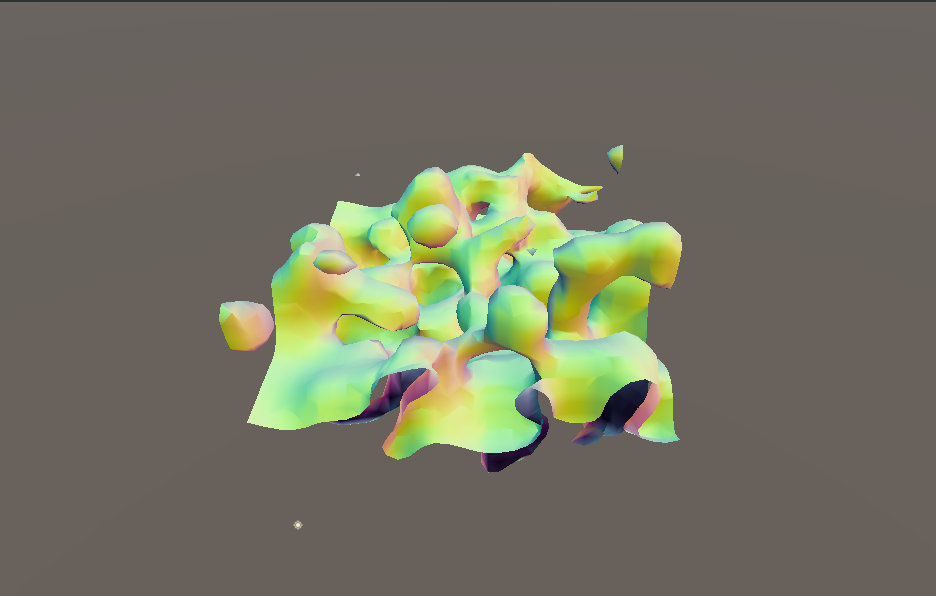
Another use of GPU Driven Rendering in Unity, this time for the Marching Cubes algorithm on the GPU for complex procedural mesh generation. In this project, I have used compute shaders to generate complex meshes efficiently for indirect drawing. The process is optimezed to generate a vertex pool with only unique vertices alongside an index buffer for indexed drawing.
The Marching Cubes algorithm
The set of points with a constant value in a scalar field is known as an isosurface. For instance, a 3D scalar field defined by f(x,y,z) = x2 + y2 + z2 will generate a spherical isosurface of radius r when f(x,y,z) = r2.
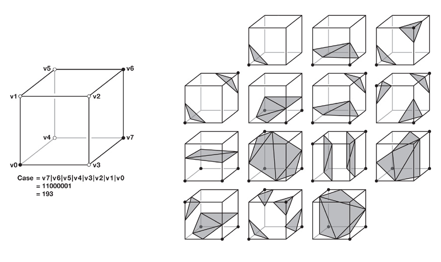
Marching cubes is an algorithm developed by Lorensen and Cline to build polygonal meshes of an isosurface of a three dimensional scalar field. In order to do that, the space is partitioned into a uniform grid and we sample the density at the corners of each cubic cell. based on the density value sampled, we can mark edges where the value is greater than the constant isosurface value. This will generate one of 256 possible cases and for each case we can find the total number of unique vertices and triangles within the cell by using lookup tables. The figure below ilustrates the marking process as well as the possible cases:

For this project, I have used nvidia’s GPU gems 3: Chapter 1. Generating Complex Procedural Terrains Using the GPU as a reference. However, instead of using geometry shaders, I decided to restructure the entire algorithm arround compute shaders.
Indexed Triangle Generation
The main difference from nvidia’s GPU gems article is that I use compute shaders to replace the vertex streaming from geometry shaders. This comes with the advantage that we can choose how the vertex buffer will be laid out. This case is another one where nvidia’s Work Efficient Parallel Prefix Sum (Scan) comes in handy, since we can use it to output an offset buffer that can easily map our vertices into the final vertex buffer. These offsets can then be used again when creating our index buffer, thus reducing the total number of required passes for the algorithm.
Density Functions
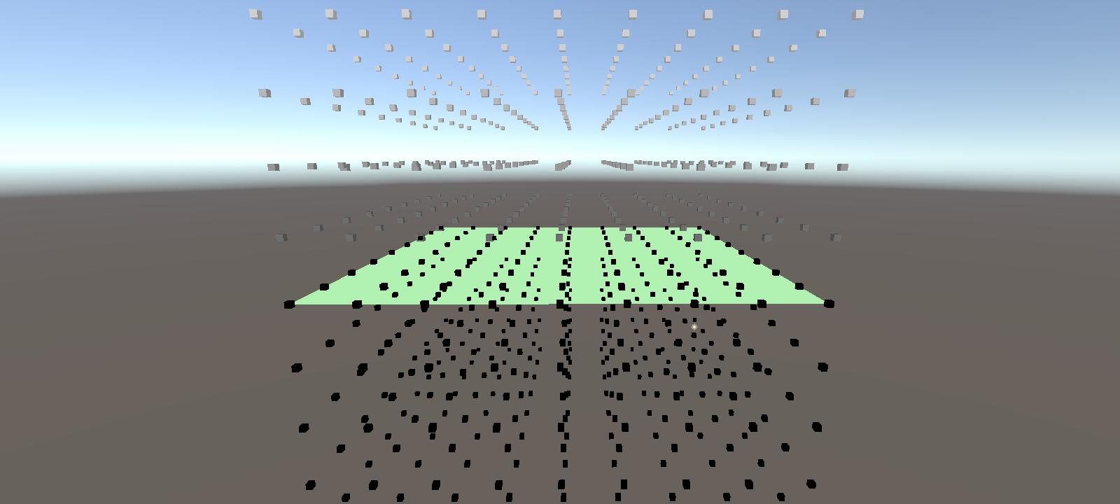
As the density function is reused when marking and when actualy generating the vertices, we calculate the necessart values in the first pass:
[numthreads(8,8,8)]
void GenDensity (uint3 id : SV_DispatchThreadID)
{
  if (max(max(id.x, id.y), id.z) < (chunkSize + 1))
  {
    uint cellID = getCellCornerID(id);

    //Plane:
    //densityVolumeOut[cellID] = (id.y - 16.0f)/16.0f;

    //Sphere:
    //densityVolumeOut[cellID] = (sqrt( (id.x - 16.0f) * (id.x - 16.0f)
    //                            + (id.y - 16.0f) * (id.y - 16.0f)
    //                            + (id.z - 16.0f) * (id.z - 16.0f))
    //                            - 8.0f)/20.0f;

    //Noise:
    //densityVolumeOut[cellID]  = SampleNoise(float3(id)/6.0f);
  }

}


